I’ve worked with electronics for a number of years now, but somehow I have not had occasion to do much reverse-engineering of existing circuits. But today I got the chance with a nice LPBi14042 bicycle front light that was acting up a bit. Here is the PCB:
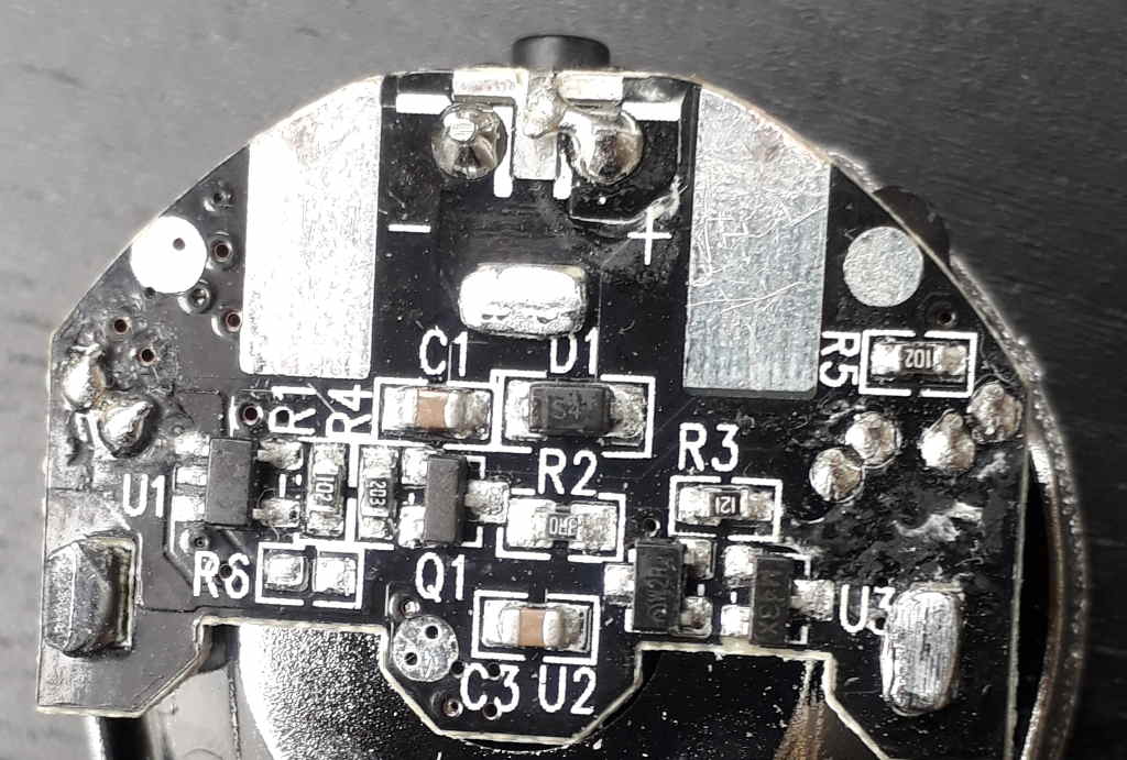
The PCB is nicely laid out and quite compact. Not visible on the back side is mounted the main white SMD LED as well as a few through-hole components (capacitor, inductor, indicator LED). At the top can be just seen the tip of the on/off pushbutton sticking out.
I was not able to identify the ICs except for the rightmost U3 which is an XC61C voltage detector. But after beeping the circuit through and drawing up the schematics it seems clear enough:
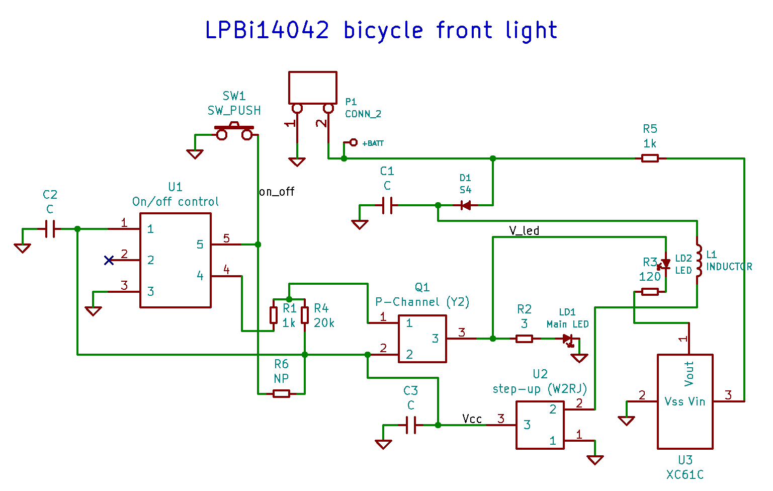
The schematics is laid out with component positions and orientations approximately the same as on the PCB, for easy reference.
This bicycle light seems reasonably well constructed. There is a DC-DC step-up converter U2 to supply the needed voltage for a white LED from two AA-batteries which will be well below their nominal 2 x 1.5V before being fully drained. There is even a “battery low” indicator (red LED on the back of the PCB not visible in the picture). This is actually useful for a bike light like this; because of the step-up converter, the light will drop off very sharply at the very end of the battery life, with little advance warning. So a battery-low warning helps not getting stuck with no light on the bike on a late night. The indicator light is though somewhat well hidden, and hard to spot perhaps.
Some details of the circuit:
- The main SMD white LED LD1 is mounted on the back side of the PCB.
- Solder pads for a through-hole component is visible on the left (C2 capacitor), and two on the right (red indicator LED LD2 and inductor L1 for the step-up converter).
- Power is supplied from two AA batteries through the two big contact areas at the top (marked P1 in the schematics).
- Diode D1 protects against reverse polarity, easy mistake to make by putting in batteries the wrong way.
- U2 is the step-up converter. It is marked “W2RJ”, but I was not able to identify it. There are however similar ICs available. It is a very simple model with just three pins. The similar ICs I found have a requirement for an external Schootky diode, however this is not visible on this PCB. Maybe this particular step-up converter has a built-in diode?
- Q1 is just marked “Y2” which does not say much. But from the schematics it looks like a P-channel FET. Its gate (pin 1) is pulled high through R4 so the transistor is by default off. The drain (pin 3) drives the LED.
- U1 is some kind of on/off power control IC. It is connected to pushbutton SW1 through input pin 5. When the button is pushed to pull the input low, U1 latches its output pin 4 alternately low and high. This output drives the gate of the FET through series resistor R1.
- Once turned on, the FET Q1 drives the main LED through the current-limiting 3 ohm resistor R2. So there is no proper constant-current driver IC or circuit to drive the LED, which is normally preferred. Hopefully the step-up converter can keep a sufficiently constant voltage over the whole range of battery discharge to make the simple current-limiting resistor approach sufficient.
- U3 (marked M43X on the package) is a Torex XC61C voltage detector. Its Vin input is connected directly to the battery voltage. If the voltage is detected lower than the threshold, the output Vout is driven low. In the circuit this is connected to drive a red indicator LED through current-limiting resistor R3, thus functioning as a “battery low” warning. The datasheet for XC61C says M43 means a 2.9V threshold, which seems a little high, not sure if I’ve found a wrong datasheet, or if it is just made like that.
- Not populated resistor R6 seems to be a pull-up for the on/off pushbutton. Apparently this is not needed (internal pull-up in U1?).
- Since there is no enable pin on the step-up, it seems to be always on, and the circuit relies on the pull-up R4 to keep the FET closed and the current out of the step-up output at zero. I wonder if this is enough to keep leakage very low; otherwise the bicycle light might end up draining the batteries during periods on no use.
This PCB was reasonably simple, and nicely designed with component references Rn/Cn/Un/etc. So it was simple to decipher and understand, and a nice and interesting experience.