March 29 2014 is Arduino day, also in Labitat. This is a good opportunity to describe my LED-cube:
This LED-cube pulls a number of tricks to get the most out of just a single normal Arduino Uno. A meager 16 MHz and 2048 bytes of RAM goes a long way with sufficient ingenuity and creativity. Here are some highlights:
- 12-bit PWM, 16 grayscales non-linear.
- Animations generated on-board, read from SD-card, or streamed over USB.
- 178 Hz refresh rate, transferring 3 Mbits/s of data to the LED driver shift registers.
- 50 Hz animation framerate, receiving 269kbit/s of animation data over the serial port.
- Approximately half of spare CPU time available for on-board generation of animations.
- Multi-processor Arduino! Uses the Atmega 16U2 USB-handling chip on the Arduino Uno as a second processor, reading animations from an SD-card.
- Hand-crafted assembler to speed up time-critical parts.
LED-cube basics
One of the first questions I get when I show the LED-cube to people is: How is it possible to turn individual LEDs on and off? After all, it looks like everything is connected to everything. Here is how it works.
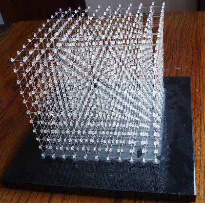
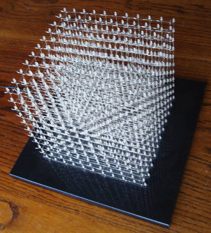
The LEDs in the cube are organised into columns. The 11x11x11 cube thus has 11*11=121 columns, each containing 11 LEDs. Let us first see how a single column works:
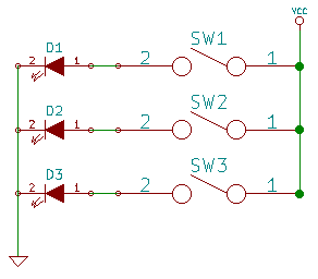
All the cathodes are tied together and connected to ground. Each anode can be individually connected to the supply voltage using one of the switches. This allows to turn on one LED by connecting the appropriate switch.
Now let us see how it works with multiple columns:
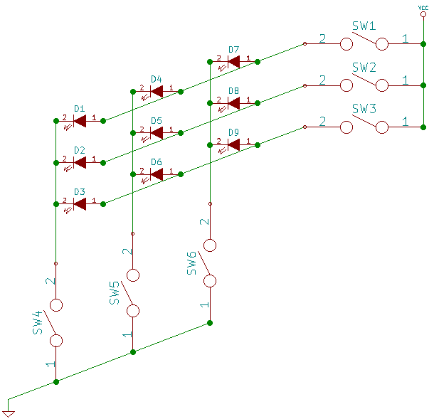
The anodes of one LED from each column are all tied together and connected by a single switch to the supply voltage. The columns now have each a switch connecting them to ground. Now, to turn on eg. D5, we would connect SW2 and SW5. To turn on in addition D8, we would connect in addition SW6.
But what if we want to turn on D1 and D5? For this, we need to connect all of switches SW1, SW2, SW4, and SW5. But that turns on also D2 and D4. Thus, to control every LED independently, we need something more.
The answer is multiplexing. We only ever have one of SW1, SW2, and SW3 turned on at the same time. This allows to individually control each LED in one level of the columns using the bottom column-switches. Then shortly after (half a millisecond in the 11x11x11 LED-cube), we turn off that switch and turn on the switch for the next level, at the same time flipping the column-switches as appropriate for controlling the LEDs at that level. By doing this quickly enough, the human eye is too slow to perceive any flickering, and we get the illusion that each LED is turned on or off independently, at will.
Using multiplexing, the required number of switches and connections is greatly reduced. In the 11x11x11 cube, we need only 11*11=121 switches for the columns, plus an additional 11 swiches, one for the anodes in each horizontal layer. (“Only”, compared to 11*11*11=1331). In the cube structure, the column connections are the vertical structures, and the horizontal structures connect the anodes in one layer each to a switch through 11 extra columns at the back of the cube.
Soldering the LED structure requires some soldering skills, but with 1331 LEDs to do, such skill will be naturally aquired before the end of the project. Most especially, patience is needed. There are several good pages on the internet describing in detail how the LEDs are soldered together for an LED-cube, here is one, for example.
The layer/anode switches are implemented using 11 P-channel MOSFETs, controlled directly from 11 GPIO pins on the Arduino. The column switches are implemented using 8 TLC5940 LED driver ICs. The TLC5940 has the additional benefit of being able to accurately control how much current each LED receives, as well as being able to dynamically adjust the LED brightness using 12-bit PWM (4096 intensity levels).
Electronics
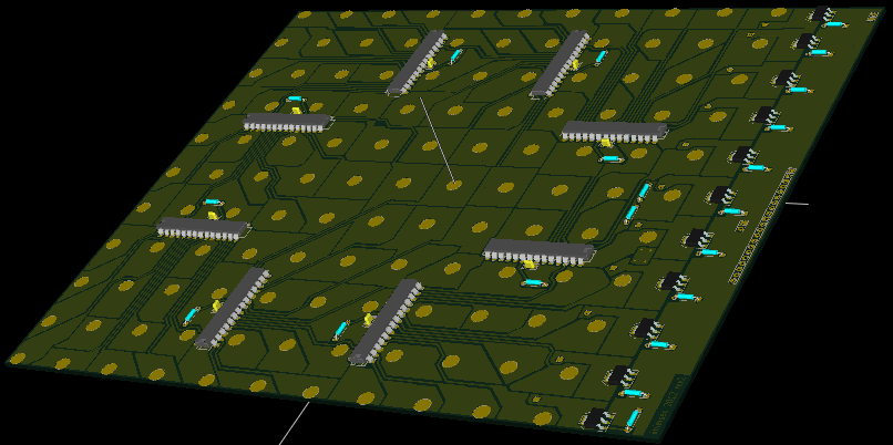
The electronics sit on a 20cm-by-20cm PCB located below the base of the LED-cube. The picture shows the PCB from the bottom side; the LED columns (and the connection to the 11 layers) enter through the yellow holes from the top, are bent 90 degrees, and soldered to the copper pads.
The 8 ICs spaced around the middle are the TLC5940 LED drivers, connected to each LED pad. The connections are made for ease of PCB layout, so the software has a lookup table that maps each LED column to the TLC5940 output to which it is connected. Along the right of the board are seen the 11 P-channel MOSFETs that supply the voltage for each layer, one at a time.
At the very right edge is seen the connector to the GPIO pins on the Arduino Uno. Originally, the cube was controlled by an actual Arduino Uno device, connected to the cube with a ribbon cable. But the current version uses instead a custom control PCB with a small, narrow footprint that just fits below the base of the LED-cube. This way all the electronics is hidden away below the very narrow base, resulting in a very nice elegant presentation of the cube:
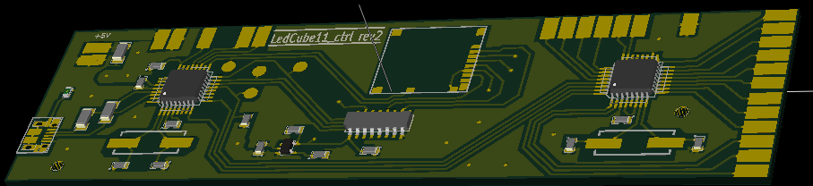
This control PCB is similar to an Arduino Uno; but it is stripped for anything not needed for the cube, and has a micro-SD card slot and level-shifter soldered directly on the board (originally an small external micro-SD board was connected to the Arduino Uno). The micro-SD slot (not shown on the drawing) and the level-shifter are in the middle. To the left is the USB-connector and the Atmega16U2 chip that handles the USB. To the right is the Atmega328 that runs the main code for the LED-cube. The connections to the main PCB are soldered to the pads along the right and top-right.
The PCBs were layed out with KiCAD; see the end of this article for links to source code. The main board was manufactured with the PCB CNC milling machine we have at Labitat. The small Arduino-clone PCB was manufactured by the SeeedStudio Fusion PCB service.
Software
The LED-cube has 1331 LEDs, each of which can be PWM’ed for 16 different levels of brightness, from 0 (turned off) to 15 (fully on). The state of all the LEDs is stored in a framebuffer; with 4 bits per LED that amounts to 666 bytes. To avoid flicker, double-buffering is needed. With 2kByte of memory, the Arduino has just room for two framebuffers, with a bit of memory to spare for the rest of the activities.
The software has two main tasks to control the LED-cube:
- Every 20 milliseconds, load one of the frame buffers with the next frame of the animation being played, for an animation framerate of 50 per second.
- Every 500 microseconds, turn on the LEDs in one layer of the cube with the appropriate intensity, by programming the TLC5940 driver chips with the correct PWM value and turning on the power to that layer through the next P-channel MOSFET; resulting in a refresh rate for the entire 11-layer cube of around 178 Hz.
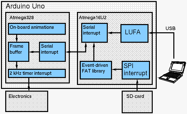
The loading of animation frames into the framebuffers can happen from three sources: They can be loaded from an SD-card, they can be streamed from a PC over the USB port, or they can be generated by code on-board the Arduino itself. The refresh of the LED intensities happens in a timer interrupt, using the SPI device on the Atmega328 to communicate with the TLC5940 driver ICs. The individual steps are detailed in the following sections.
Communicating with the TLC5940 LED-driver ICs.
The TLC5940 LED-drivers need an external PWM clock; this is supplied from the arduino from a timer in PWM mode. An 8 MHz PWM-clock is used; this is the fastest clock that the 16 MHz Atmega328 can generate. One PWM cycle is 4096 PWM clocks, as the TLC5940 uses 12-bit PWM. It is important to always let the TLC5940s run an integral number of PWM cycles; else the brightness of LEDs will be off. So a timer-interrupt runs every 4096 PWM cycles to trigger the TLC5940s; this works out to about 2 kHz for switching each layer on and off, or 178 Hz refresh rate for all 11 layers. The TLC5940 ICs employ a latch, so the timer interrupt first latches new data to get stable PWM timing, then goes to work to send out new data to the driver ICs to be ready to latch at the next timer interrupt.
The 8 TLC5940 ICs have a total of 128 outputs, each of which needs 12 bits of PWM data. That amount to 1536 bits or 192 bytes of data to send to the LED drivers in each refresh cycle. One refresh cycle has a total of 8192 CPU clock cycles, and we need to leave as much as possible of those for generating / downloading the next frame of animation, so this step is carefully optimised for speed.
The data is shifted into the TLC5940s using data and clock pins, so we can use the Atmega328 SPI device in master mode. The maximum speed possible for the SPI device is using an 8 MHz clock, so that means 16 CPU cycles per byte plus a couple extra to load the next byte, as the SPI device is only single-buffered, for a total of around 3500-4000 cycles of the 8192 available.
But we also need to prepare the data to send to the LED drivers. This involves a few steps per TLC5940 output:
- Fetch from a lookup-table the index of the LED that is connected to the next TLC5940 output on the PCB (remember, those connections are in more or less random order to optimise the PCB layout).
- Use that index into the frame buffer to fetch the 4-bit value that gives the required brightness of the LED.
- Use the brightness value to index into another lookup table, which maps each possible brightness into the corresponding 12-bit PWM value. This mapping is made non-linear to improve the dynamic range available with just 16 different levels, as the lower PWM values are perceived by the human eye to be much easier to distinguish than the higer values.
- Pack the 12-bit values of two consecutive outputs into three bytes suitable for transmission on the SPI device (it is thus easier to do two LEDs at a time, producing three whole bytes of SPI data for each loop iteration).
As it turns out, these operations together take something like 60 CPU cycles for two LEDs or 20 cycles per SPI output byte, which is another 3500-4000 cycles.
With 8192 cycles total, we cannot afford to first spend 4000 cycles preparing the data, then spend another 4000 cycles sending the data out. So we use a trick. By writing the code in assembler and carefully timing each instruction, we can overlap the two operations, inserting into the data generation algorithm instructions to feed the next byte of data to the SPI at exactly the points in time where they are needed.
In C it might look something like this, with the data generation algorithm on the left and the SPI data output on the right:
    // Loop over the TLC5940 outputs two at a time
    for (o = 127; o >= 0; o = o - 2)
    {
      // Find index into frame buffer
      led_idx = led_map[o];                                           // Output one byte
                                                                      SPDR = byte1
      // Load the 4-bit intensity from the frame buffer
      if (led_idx & 1)
        intensity = frame_buffer[(offset + led_idx)/2] & 0xf;
      else
        intensity = frame_buffer[(offset + led_idx)/2] >> 4;

      // Loopup the 12-bit PWM value from the intensity.
      pwm1 = pwm_lookup[intensity];
                                                                      // Output one byte
      // Same for second output                                       SPDR = byte2
      led_idx = led_map[o+1];
      if (led_idx & 1)
        intensity = frame_buffer[(offset + led_idx)/2] & 0xf;
      else
        intensity = frame_buffer[(offset + led_idx)/2] >> 4;
      pwm2 = pwm_lookup[intensity];

      // Pack the two 12-bit PWM values into three SPI bytes
      byte1 = pwm1 >> 4;
      byte2 = (pwm1 & 0xf) << 4 | (pwm2 >> 8);                        // Output one byte
      byte3 = pwm2 & 0xff;                                            SPDR = byte3
However, the algorithm is not really expressible in C. The instructions to output the data bytes to the SPI device need to be placed so that the bytes to output have been computed and the timing between them must be just right so that they happen as soon as the SPI has completed the last transfer (but no sooner, or the previous byte will be corrupted). The actual assembler code can be seen here, in the function shift_out_frame_spi(). The comments in the function mark the cycles spent on each instruction so that the SPI output can be spaced out with the correct timing.
This way, the code is able to send out data for two TLC5940 outputs in around 63 CPU cycles, or about 4000 cycles total per refresh cycle, leaving half the CPU time free for handling the frames of animation, which is nice. I think this is a rather interesting programming technique. It is a bit like multi-threading, but with the instruction scheduling hardcoded explicitly into the program.
Serial reception
In addition to generating some animations on the Arduino itself, they can be streamed into the Atmega328 through the serial port. The protocol is mostly the raw binary data in the framebuffer (4 bits per LED), plus a couple of control bytes like start/end marker, frame number, and checksum, to facilitate synchronisation between sender and receiver. If the receiver detects that the frames are not received correctly, it sends back an error byte; the sender notices this and pauses the data for a few frames, and the two ends re-synchronise. This is a simple but effective technique that allows for efficient transfer of the data.
One frame of data on the serial port is 672 bytes inclusive control bytes. At 50 frames of animation per second, that amounts to 33600 bytes or 268800 bits per second. The serial port is run at 500000 bits per second; with the overhead of start and stop bits, that still allows to comfortably transfer the required data at the desired rate.
However, with this rather high data rate, care is needed to be able to process all received bytes sufficiently fast that no data is lost. The Atmega328 has just a single byte receive buffer. At 500kbps, a new byte arrives 50000 times per second, meaning that we have just 320 CPU cycles to process a received byte before it will be lost due to being overwritten by the next byte.
To handle this, a serial receive interrupt is employed. The interrupt is triggered whenever a byte is received by the serial device on the Atmega328, and we need to ensure that it will be serviced within at most 320 CPU cycles. The Atmega328 does not have interrupt priorities, but it does support nested interrupts. Interrupts are automatically disabled whenever an interrupt routine is invoked, but that routine can re-enable interrupts explicitly, and this will allow another nested interrupt to be handled before the first one is completed. Indeed, this is absolute necessary to do in the cube in the refresh timer interrupt, as this runs for several thousand cycles. Nested interrupts work well, but they require a lot of care; race conditions between conflicting interrupts can be quite hard to debug, and one also needs to protect against runaway interrupts (where the same interrupt is invoked recursively and repeatedly on top of itself until the stack is overrun).
With more than 30000 serial interrupts per second, we also want to make the code for the serial interrupt handler as efficient as possible. Unfortunately the AVR architecture does not exactly shine in this respect. Here is how a typical interrupt routine looks as generated by GCC:
    push    r1
    push    r0
    in      r0, 0x3f
    push    r0
    eor     r1, r1
    push    r16
    push    r17
    push    r18
    push    r19
    push    r20
    push    r21
    push    r22
    push    r23
    push    r24
    push    r25
    push    r26
    push    r27
    push    r28
    push    r30
    push    r31

    ...

    pop     r31
    pop     r30
    pop     r28
    pop     r27
    pop     r26
    pop     r25
    pop     r24
    pop     r23
    pop     r22
    pop     r21
    pop     r20
    pop     r19
    pop     r18
    pop     r17
    pop     r16
    pop     r0
    out     0x3f, r0
    pop     r0
    pop     r1
    reti
That is no less than 40 instructions just as pre/post-ample, most of which take two CPU cycles each.
Of course, in an interrupt routine, we do need to save/restore all registers used. However, most of the invocations of the serial interrupt do not need to use more than a few registers; just enough to grab the next byte from the serial device and put it into the frame buffer. Only for the control bytes at the start and end of a frame do we need more registers for more complex processing. Unfortunately, GCC always generates the code to push and pop all the registers unconditionally, even though some of them are only used in rarely executed code paths (the large number of callee-save registers in the AVR calling convention plays a part of the problem here).
The solution is to write the serial interrupt in hand-optimised assembler. In the fast path, where we are just stuffing a byte into the framebuffer (and computing a checksum on-the-fly, incidentally), we only need to save three registers (plus the condition codes). That all can be done in just 26 instructions. Then in the slow path, the assembler code goes on to push all remaining registers and defer to the more complex processing in a C function.
The actual code can be seen here. The assembler code for the fath path is in serial_interrupt_rx_naked(), while the slow path is in the function serial_interrupt_slow_part().
Reading animations off SD-card
While some of the animations can be computed on-the-fly on-board the Arduino, some of the more complex ones are too much for the puny Atmega328 to handle. The problem usually is not so much processing speed as memory: With a total of just 2048 bytes of RAM, most of which is already reserved for frame buffers and stack space and various global variables, not a lot is left to keep track of stuff like position and velocity of lots of particles in the fireworks animation or similar stuff. Using the serial port, we can generate the animations on a PC and stream them to the cube; however it is also nice to be able to run the cube completely standalone: just plug it into power (or even run it off a battery) and it runs and displays animations on its own, without needing a laptop on tow. Thus the idea was born to pre-compute the animations and read them from an SD-card.
Now, at just 672 bytes per frame of animation, a 4 GB SD-card can store more than one day worth of animation, so this is fine. The problem however is that we are running short on IO as well as on memory. Mostly all available pins are already needed to control the 11 MOSFETs and to communicate with the TLC5940 ICs. Besides, the SPI device, which is normally used to communicate with an SD-card, is needed for communication with the TLC5940s, and the serial device (which can also do SPI) is needed for the USB-to-serial interface. So what can be done?
Let us take a closer look at the Arduino Uno, the top left corner near the USB connector:
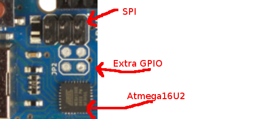
What we see here is the Atmega16U2 IC, which comes pre-installed with firmware (based on LUFA to control the USB port and function as USB-to-serial proxy. It is however perfectly possible to modify that firmware to do additional things – such as connect an SD-card! Furthermore, just next to it we have the ICP header – this is normally used to program the flash on the Atmega16U2, but it has the pins for the SPI device, which is just what we need to communicate with an SD-card over SPI. And finally, we even have unsoldered pads with four spare GPIO, one of which we will need as a chip select pin for the SD-card.
So as it turns out, the Arduino Uno is in fact a multi-processor device! The LED-cube exploits this, connecting the SD-card to the ICP pins and spare GPIO of the Atmega16U2 MCU and hacking the USB firmware to handle the SD-card. If there is no activity on the USB port, the hacked firmware will check for the presence of an SD-card with animation data on it; if found, data will be streamed from the SD-card over the serial port to the Atmega328, which will handle the serial data the same, whether it originates from a PC at the other end of the USB, or from the SD card.
Now, using the Atmega16U2 in this way does present some challenges. The Atmega16U2 is only equipped with a meager 512 bytes of RAM, some of which is already needed for LUFA data and so on. The data on SD-cards is read one sector at a time, and a single sector is 512 bytes, already more than the RAM we have left. Most libraries for reading SD-cards and dealing with the FAT filesystem on them is based on reading one sector at a time into a buffer in RAM and processing it there; that just will not work when we have only a few hundred bytes of RAM to spare for the task.
Furthermore, most SD-card/FAT libraries are written in a traditional blocking style. That means, they provide some function you can call to read data from a file on the SD-card. Such function will take a memory buffer (which we do not have the memory for), and it will not return to the caller until all of the requested data has been read, which means waiting at least for one sector to be read. That does not integrate well with the existing USB/LUFA firmware, which runs its own main loop that waits for activity on the USB device and does not return to the main program unless there is some activity to respond to.
To overcome these challenges, I wrote a small event-driven FAT library, seen in ev_fat.h and ev_fat.c. This library works in a streaming fashion, without any blocking. It never needs to process SD-card data in a memory buffer. Instead, the caller feeds it the bytes read off the SD-card one by one, and the library processes the bytes as they are received, keeping track of its state in a small data structure, and returning status information back to the caller about which sectors from the SD-card to read next.
    /*
      Open a named file in root dir of FAT file system.
      Before calling, st->state must be initialised to 0.
      Then the function must be repeatedly called until it returns
      EV_FILE_ST_DONE or negative error code EV_FILE_ST_E*.

      The returned status tells the next action to take, see comments in struct
      ev_file_status for details.

      When EV_FILE_ST_DONE is returned, the first sector of the file, and the
      length in bytes of the file, is returned in st->st_get_block_done.
    */
    int
    ev_file_get_first_block(const char *filename, struct ev_file_status *st);

    /*
      After opening a file, this finds the next sector in the file. When calling
      this function, st->st_get_block_done must be set to / retain the value set
      by the previous call to ev_file_get_first_block() /
      ev_file_get_next_block().  After EV_FILE_ST_DONE is returned the new sector
      number is then found in st->st_get_block_done.
    */
    int
    ev_file_get_next_block(struct ev_file_status *st);

    /*
      This callback is used to stream bytes read as a response to a request
      EV_FILE_ST_STREAM_BYTES. Each byte requested must be passed in, in
      sequence. The return value is true if no more data needs to be streamed;
      in this case it is permissible, but not required, to stop the read early
      and not stream the rest of the requested bytes.
    */
    int
    ev_file_stream_bytes(uint8_t byte_read, struct ev_file_status *st);
With this library, the reading of the SD-card can be handled completely inside an SPI interrupt routine, without disturbing the LUFA USB code. Each time a byte has been processed in the communication between the Atmega16U2 and the SD-card, the SPI device triggers the SPI interrupt. This interrupt processes any byte received, updates its internal state, and loads the next byte to be processed into the SPI device data register. The interrupt is seen in ISR(SPI_STC_vect). The code handles the protocol to connect to and initialise the SD-card, and then takes care of reading in sectors and passing the bytes to the event-driven FAT library.
When we get to actually read real file data out of the SD-card, we stream it directly to the serial port (where it will be received and processed by the Atmega328), to avoid the need for large memory buffers. The existing firmware already has a small FIFO used to buffer data for sending down the serial line. We re-use that, so that when no data is available from the USB for a few seconds we start filling up the FIFO with data from the SD-card instead. A serial device interrupt is triggered whenever the previous byte has been fully transmitted down the serial line; this interrupt fetches the next byte from the FIFO and loads it into the serial transmit data register. If the SD-card delivers data faster than the 500kbps serial line can transmit, we temporarily pause the SPI communication and resume it once the serial interrupt has made room for more data in the FIFO; the SD-card specifications explicitly mention this as a supported way to operate, precisely to help very small microcontrollers be able to process data without requiring excess buffering capabilities.
The end result is an extended USB firmware that retains all the original functionality (streaming serial data from a PC and so on; even flashing the Atmega328 over the serial port still works). And in addition, if the USB is idle and an SD-card is present, data is instead continuously streamed from the card, allowing completely stand-alone operation of the cube.
The code to handle all this does end up rather intricate, as can be imagined. Apart from the need to write a custom FAT-reading library, the precise timing between the different interrupt handlers end up requiring quite a lot of careful coding and debugging. But in the end, I found that code to be quite an interresting exercise, and fun as well – and this is after all a for-the-fun-of-it type project.
Calculating the animations
One of the nice thouches of the visuals this LED-cube in particular is the availability of 16 different intensity levels. This allows for some nice effects, such as fading the LEDs in-out to give a warmer, light-bulb-like perception, and using anti-aliasing to greatly reduce the disadvantage of the very limited 11-by-11-by-11 resolution.
All the animations are computed by this C++ program. The code is mostly a lot of math using vector computations, trigonometry, random number distributions, permutations, physics simulations and other nice stuff. The end result is a sequential stream of animation frames that can be send directly to the LED-cube over the serial port, or stored in a file on an SD-card for stand-alone playback.
Conclusions, and source code
If I were to do this project today, I would probably use an ARM microcontroller like the STM32F4. Such a microcontroller is easily able to handle driving something like this LED-cube without the need for any special tricks due to its much larger memory and performance. But this was just a for-fun project, and it was interesting to see just how much could be squeezed out of the very popular AVR-based Arduino. That is quite a lot, as it turns out.
The nice thing about the LED-cube is: On the one hand it involves lots of tricky programming and advanced technology. On the other hand it has an immediate appeal to many different kinds of people, as is seen whenever we take it on display and it immediately draws the eyes of people passing by. The technology aspect is much harder to appreciate than the visual aspect. I have wanted to write up this article describing the project for some time, in all the gory technical details. I hope a few people will be able to use this write-up to appreciate the technical side as well as the visual side.
All of the code and design files for this project are available on Github under an open source license (GPL):
- KiCAD files for the main PCB.
- KiCAD files for the control board PCB (Arduino Uno clone).
- Source code for the control program running on the Atmega328.
- Modified USB firmware for the Atmega16U2 reading from SD-card.
- Source code for the program that computes the individual frames of the animations.
- Source code for an OpenGL-based viewer for the Ledcube animations.
In addition, the Arduino code needs these header files by Esmil for easy access to Atmega registers and so on.
Amazing and great in so many ways!
I must first and foremost congratulate you on an awesome project, but not only that – it’s complete with a comprehensive documentation and even if I am an avid programmer (though mainly not in C# or C++, but that is slowly changing with my microcontroller so) there are lot of things to be learned through your codes.
I was basically out ‘prowling’ for information about fast UART communication, but this served a great purpose too and is now bookmarked.
Thank you, not only for your post, but also for making everything readily available for download etc.
As I am writing this your post is over 2yrs old and it kind of bothers me that no one else have seen and commented on it.
I wish you a very good end of the year and once again; thank you for sharing your hard work!
Best regards, Mattias Lindstrand
Re: Amazing and great in so many ways!
Thanks for the kind words, I’m glad you enjoyed the article.
Great Project!
An ambitious project, with excellent source code. I can learn a lot from it.
I noticed coordinates are double precision. With only a 0-10 data range, is double precision really needed? It does not seem to affect the speed of the display, but memory can also become an issue.
Thanks
Re: Great Project!
I think you are right, that double precision is not needed. But it is only used in mk_animation.cc, to pre-compute animations on a PC, where memory or efficiency is not an issue.
The pre-computed animations are stored memory-efficiently, using 4 bits per LED (two LEDs per byte).