[Here is a PDF version for readers whose browser does not understand MathML.]
The Simplex Noise (or Improved Perlin Noise) algorithm uses a somewhat mysterious “skew factor” of . I did not find any really satisfactory explanation for this factor in the descriptions of Simplex Noise that I read. But I managed to work it out nevertheless, which I thought was a fun exercise and worth a quick write-up.
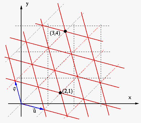
Simplex noise is constructed by assigning random values to each point in a simplex grid. The simplex grid is a tiling of the plane using rhombuses, each rhombus consisting of two equilateral triangles. See the figure on the right.
Given a point (expressed in normal rectangular coordinates), we first transform the coordinates into expressed in the simplex grid. Then we take the integer parts of u and v to find the corners of the containing equilateral triangle, and take the random values assigned to these corners. The “noise value” of the original point is then some suitable interpolation of these values with respect to the distance from to each corner.
The implementation of this algorithm is explained in detail in several places. The code to transform into and back out of the simplex grid might look like this:
final double F2 = 0.5*(Math.sqrt(3.0)-1.0);
double s = (xin+yin)*F2;
int u = fastfloor(xin+s);
int v = fastfloor(yin+s);
final double G2 = -(3.0-Math.sqrt(3.0))/6.0;
double t = (u+v)*G2;
double X0 = u+t;
double Y0 = v+t;
So the question is, where do these funny factors F2 and G2 come from?
To understand this, let us first consider the general form of the transformation from simplex coordinates in the grid spanned by and to the rectangular coordinates . It is
where and . So this requires 4 multiplications in the general case.
However, we can freely choose which simplex grid to use! So we can try to choose one that reduces the computational work needed.
First, we can choose the orientation of the grid so that and are symmetric around the diagonal . Then and , so we can write the transformation as
Second, we can choose the scale of the grid so that , and then we get simply
This is exactly the form we see in the above code snippet, with G2 being the name for the constant . We can work out from this that the vectors that span the grid used by the code are
The interested reader is encouraged to check that , , and all have the same length, so that the triangles that form the grid indeed end up being equilateral.
Working out the inverse of the transformation (again a good exercise for the interested reader) leads to another transformation of the same simple form, this time with the constant as seen in the code.
So I believe this is the explanation of the mysterious factors F2 and G2 in the example code found by Google searches on the net. They arise from the choice of the simplex grid to use. This choice is made to make the associated coordinate transformation use only a single multiplication, rather than the four required in the general case. This makes the implementation of the algorithm more efficient. Pretty clever, right?